A pH Measurement & Control System for the Planted Aquarium
Page 6
![]()
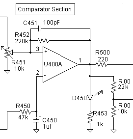
Comparator

The signal from the amplifier is fed to the comparator via R450 and C450. These two components form a simple low pass RC filter with a 3 dB point of about 3 Hz. Again, these noise-reducing components are optional but recommended. Potentiometer R451 sets the voltage at which the CO2 turns on and off. Since this comparator gets the uninverted signal straight from the amplifier, this voltage must be set to (for example) 7.2 to get a trip point of pH 6.8.
As was mentioned earlier, there is 0.1 volt of hysteresis here to prevent the comparator from chattering on and off at the set point. If the CO2 is set to turn on at pH 6.8, it will not turn off again until the pH drops to 6.7. This type of circuit is described in detail in both the IC Op Amp Cookbook and The Art of Electronics. Briefly, the hysteresis equals the output swing of the op amp (about 10.6 volts) times the parallel value of the two sides of voltage divider potentiometer R451, divided by R452. For example, if R451 is set to 6300 and 3700 ohms for a divider voltage of 7.2, the parallel resistance value is 2330. This value is then divided by that of R452: 2320/220,000 = 0.0106. The op amp's output swing of 10.6 volts times 0.0106 gives a hysteresis of 0.1 volt. This value shifts little over the range of pH's aquarists are likely to use. Doing the preceding calculations isn't necessary to build the circuit, of course. The circuit designed by Jim Hurley (see the link at the bottom of the page) uses a different and somewhat easier to understand approach at this stage at the cost of merely another IC.
C451 is a speedup capacitor that helps the comparator's output to "snap around" once the output starts to change.
R500 is an isolation resistor, included in case there is a long wire run to the next stage (the actuator). To be effective, it should be kept close to pin 1 of U400A.
D450 and R453 are the front panel "CO2 is On" light. Note that if this LED flickers near the turn-on / turn-off point, it is evidence of noise on the signal. Chances are the circuit will still work fine, but if the noise-reducing circuitry discussed earlier has been left out and this symptom is seen, it should be taken as warning to go ahead and install it.
The 22k/10k divider (R00 & R00) is an optional takeoff for those using my pumped CO2 system. (The divider output goes to pin 4 of the pump controller 555, which must be disconnected from Vcc.) You don't need to include these two resistors if you're not using the pumped system. (Conversely, those using the pumped system can skip the next section.)